

Finger Lakes Instrumentation, a divison of IDEX Health & Science LLC
1250 Rochester St.
Lima, New York 14485
1250 Rochester St.
Lima, New York 14485
Phone: 585-624-3760
Email: IHSKeplerSupport@IdexCorp.com
Web: www.flicamera.com
Email: IHSKeplerSupport@IdexCorp.com
Web: www.flicamera.com
©2023 IDEX Health & Science LLC
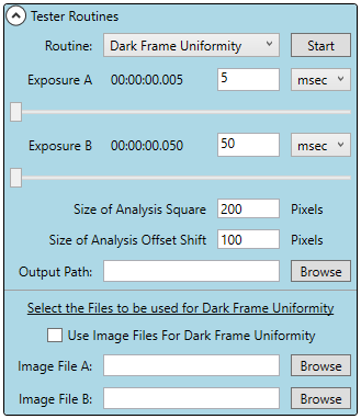
Dark Frame Uniformity (Figure 1)
The Dark Frame Uniformity function is designed to quantify Dark Current
Growth across the sensor by taking two dark exposures of differing times and
determining the difference in the pixel values in user controlled regions.
Exposure
Set the two exposure times for Exposure A and Exposure B either
numerically or using the slider bar.
Size of Analysis Square
Size of Analysis Square determines the size of the square region that will
be used to calculate the Mode values throughout the image.
Size of Analysis Offset Shift
Size of Analysis Offset Shift is the distance that each region will be shifted
when calculating subsequent Mode values throughout the image.
Output Path
The output path, selected by clicking on Browse, is the location the .csv
file will be saved to once the images statistical data has been processed.
Manual or Automatic Image Processing
While the default of this function is to capture images at the time of
clicking start, it is also possible to manually tell this function what images
to use. If you would like to analyze two images that have already been
captured and saved, enter their locations into Image File A and Image File
B using the browse buttons. If both File locations are populated, Pilot will
analyze those images using the above settings. If the File locations are
not populated, Pilot will proceed to automatically capture two images and
analyze them with the above settings.
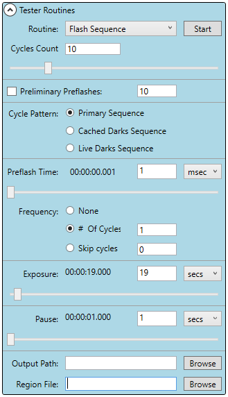
Flash Sequence (Figure 2)
This function is designed to run through an exposure sequence containing
preflash, dark exposure, and normal exposures. The function is designed to
control ghosting due to a bright flash from your illumination equipment.
Cycles Count
The Cycles Count controls how many time the function loops through the
Flash Sequence. This can be changed by using the slider or numeric
control.
Preliminary Preflashes
If Preliminary Preflashes is enabled, the number of times the light will flash
can be manually controlled. If Preliminary Preflash is disabled then the
light will flash once.
Cylce Pattern
The following Cycle Patterns are programed with the following image/flash
routines.
Primary Sequence: Preflash, Dark Exposure, 2 Normal Exposures
Cahed Darks Sequence: Preflash, 2 Normal Exposures, Pause
Live Darks Sequence: Preflash, Dark Exposure, 2 Normal Exposures,
Dark Exposure, Pause
Preflash Time
The length of time of the preflash can be controlled numerically or with the
slider bar.
Frequency:
None: Omits any preflash and replaces it with a Dark Exposure with a
duration equal to the Preflash Time
# Of Cycles: This allows you to only run the Preflash for the set number of
cycles entered, then it runs a Dark Exposure for the remaining cycles.
Skip Cycles: This runs the Preflash Exposure then skips (replaces the
Preflash with a Dark Exposure) for the set number of cycles before
running it again.
Exposure
Exposure length for the Normal and Dark images may be set here either
numerically or with the slider bar.
Pause
Pause controls the pause during every cycle in which it is included. This
can be set numerically or with the slider bar.
User Fields
Output Path: The output path can be set using the browse button. This is
where the images taken will be stored.
Region File: If you would like to only sample a subframe, a Region File
may be selected using the browse button.
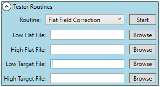
Flat Field Correction (Figure 3)
Flat Field Correction is a tool used to apply Flat Field Corrections to
images. The use of this tool is documented further at the Manual Flat Field
Corrections page.
Low/High Flat File: Use Browse to select the high/low gain master flat
frame file that will be used to flat field correct the target image.
Low/High Target File: Use Browse to select a high/low gain image that
the flat field correction will be applied to.
Please note the importance of continuity between the flat file and the target
file. The images should have the same gain settings, the same average
pixel value, and the same camera setup used to take the images with no
physical changes between the capture of the master flat frame and the
target image.
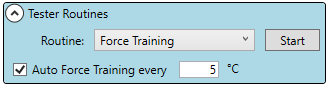
Force Training (Figure 4)
Force Training ensures that the camera is reading the sensor output during
the correct time. If the camera starts reading the output during the transition
from one byte of data to another the signal/image will be will show
irregularities. If there is an image defect it is always recommended that you
run a Force Training first to see if that solves the problem.
Auto Force Training: When enabled automatically force trains as the camera
changes temperature by the value entered.
LED Control (Figure 5)
The LED Control allows you to manually control the onboard camera LED as
well as set parameters to control the LED during an exposure.
In order to manually control the LED, use the On/Off buttons.
In order to automatically have the camera flash the LED during exposures
select the LED On during Exposure for 'LED on Time' toggle, then set the
amount of time you wish the LED to stay on for using the LED On Time by
either entering a numeric value or using the slider.
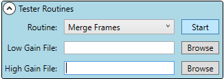
Merge Frames (Figure 6)
Merge Frames allows you to manually merge two image files together. First
select which Low Gain and High Gain image files you wish to merge by
selecting the Browse buttons. The program will use the settings in the
Imaging Parameters - Merge tab to control the merge function. Please
ensure that the settings there are adequate and then press Start. The
program will create the merged image which you can then save.
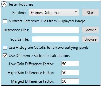
Frames Difference (Figure 7)
Frames Difference allows you to subtract one images pixel values from
another. This is primarily used to subtract a dark stacked frame from an
image to remove the pattern noise.
The image file should be added to the Source File line using the Browse
button while the reference image that will be subtracted should be added to
the Reference File line using the Browse button.
Subtract Reference Files from Displayed Image: allows you to subtract the
reference frame from the currently captured image displayed from the camera
that may or may not have been saved to a file yet.
Use Histogram Cutoffs to Remove Outlying Pixels: This uses the settings for
the Dimmest Data Threshold and Brightest Data Threshold found in
Histogram Settings (LINK) to remove the outlying pixels.
Use Difference Factors in Calculations: This function allows you to shift every
pixel in each image by the amount entered. This function is useful if the
image pixel values are being clipped at 0.
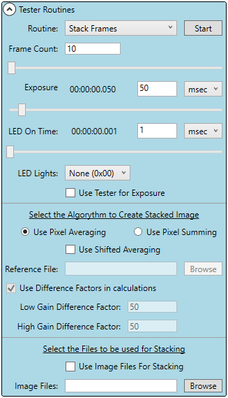
Stack Frames (Figure 8)
Stack Frames takes a number of images equal to the Frame Count and
averages the images pixel values to create a single Stacked Image. This
allows you to gain an image showing the pattern noise of the sensor while
minimizing the impact of noise.
Frame Count: Is the number of images that will be taken and averaged
together.
Exposure: Is the exposure time for the images that will be captured.
LED On Time: Is the amount of time the LED will flash for each image. The
LED can be enabled or disabled with the LED Lights dropdown list.
Pixel Averaging: Creates a Stacked image where the Pixels value is an
average of the respective pixels in each of the reference images.
Pixel Summing: Creates a Stacked image where the Pixels value is a
summation of the respective pixels in each of the reference images minus the
bias pixel times the Frame Count. In order to specify the Bias Image you
must fill out the Reference File by selecting Browse. If more than one bias
image is selected they will be averaged together before proceeding with the
correction. (Image1Pixel1 + Image2Pixel1 +...+ ImageNPixel1) -
(N*BiasPixel1) = StackedPixel1
Use Shifted Averaging: Shifted Averaging is used to minimize truncation
errors by using a 16bit value for each pixel instead of a 12bit value.
Essentially this means each pixel is multiplied by 16 before averaging.
Use Difference Factors in Calculations: If there is concern about clipping
negative values you can enable Use Difference Factors in Calculations. This
raises each pixels value by the amount entered to ensure that no values are
clipped.
Stack Images Manually: It is possible to stack images that have already been
saved. In order to manually stack images, select Use Image Files For
Stacking, then select the Image Files using the Browse button and the
program will stack the images using the above factors.
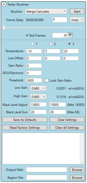
Merge Calculate (Figure 9)
In order to create a linear response across the range of a merged
image, Pilot requires a number of Merge Variables. Merge Calculate is
designed to find the best Merge Variables for the current settings of the
camera. In order to better understand the Merge Variables please review
the Merge page.
The Merge Variables are based on the Gain Pair you are using. So a
low gain of 1 and high gain of 5 will have different Merge Variables then
a low gain of 1 and a high gain of 10.
Merge Calculate is designed to automatically find the optimum settings for a
given set of image parameters. If you are operating the camera with unique
settings, running this routine will provide you with the Merge Variables
needed to produce good merge images for those settings.
To understand the variables that go into creating a merged image please see
the Merge page.
Before Initiating the Routine
Select which of the three Temperature/Line Offset settings you would like to
change. If you are not running the camera at one of the three predesignated
temperatures please select the one closest to the current temperature.
The temperature of the camera should be set under the Camera Tab under
Imaging Parameters. Merge Calculate will fill in the Temperature the camera
is running at when the program is initiated, therefore the camera temperature
should be changed far enough in advance for the temperature of the sensor to
stabilize. If you are taking long exposures we recommend allowing the
sensor to sit for 10-15 minutes, or longer, for the sensor and thermal mass of
the camera to stabilize.
Select the Gain Pair that you wish to use.
Select the MergeCalculateRegionFile.csv that was included in the installation
zip folder from the Software page. This can be selected by pressing the
Browse button next to Region File: at the bottom of the Merge Calculate tab.
Prevent exterior light from entering the camera. If your camera has a built in
shutter, it will automatically close for this routine, you should not need to take
any special precautions. If you do not have a shutter, you can place the
camera on a flat table in a dark room or on a black mat in a dark room. To
test if it is dark, take a 0 sec image and a 20 msec image. If it is dark the
mean of these two images should be the same or very close (1 count
difference). If the camera does not have a dark environment, Merge
Calculate may not produce reasonable values.
If you are concerned about ghosting effects, you can enter a frame delay
between images. Adding a frame delay can substantially increase the run
time of this routine but if you will have a long delay between image captures it
may be worth adding a frame delay to the test. If however you will be running
the camera in continuous mode or with little to no delay between image
captures it is not recommended that you set a frame delay here.
Initiating the Routine and Expectations
In order to start the routine, once the above has been completed, press the
Start Button. The routine should complete in less than 10 minutes, unless a
frame delay has been set. As the program runs you should see sdiff and idiff
values appear after each step, these values should approach 0. If these after
a few minutes these values are still increasing toward larger numbers then
you should recheck the above settings and restart the test. You can cancel
the test by pressing the Abort button, where the Start button was.
Requirements to run Merge Calculate
FLI Pilot 1.2.10 or later
KL400: Revision 4 of the FPGA Code (6 and 9 do not work)
KL4040: Revision D of the FPGA Code or later
A way of blocking light to the camera (Shutters if installed will close
automatically) If you do not have a shutter you will need to manually block light
for this process.
Tester Routines
Figure 1.
Figure 2.
Figure 4.
Figure 5.
Figure 6.
Figure 7.
Figure 8.
Figure 9.
.jpg)
Note: This program should calculate the new Merge Variables in less than 10 minutes. If you find this program does not complete after this time please check that you have blocked all light from entering the camera with its shutter or some form of light block and restart the process.
Figure 3.