Getting Started with your Kepler
Thank you for purchasing a New Kepler Camera!
The following are basic steps that will allow you to go from unboxing your camera to capturing and viewing
images.
For more information on any of the following instructions please see the links for more specific information on a
step.

Finger Lakes Instrumentation, a division of IDEX Health & Science LLC
1250 Rochester St.
Lima, New York 14485
1250 Rochester St.
Lima, New York 14485
Phone: 585-624-3760
Email: IHSKeplerSupport@IdexCorp.com
Web: www.flicamera.com
Email: IHSKeplerSupport@IdexCorp.com
Web: www.flicamera.com
©2023 IDEX Health & Science LLC
1. OS: Windows 10 - 64bit
2. Processor: i7 core preferred for best performance. i5 core is acceptable
3. Memory: 16 GB Ram, 32 or more preferred
4. An available USB 3 port (Labeled SS for SuperSpeed)

I. Computer Requirements
1. Download the latest FLI Pilot zip file from our website located here.
2. Click the Download button next to FLI Pilot Software v1.2.xx for Kepler Cameras: Windows 7/8/10 64-bit:
3. Unzip the file and run the FliPilotsSetup.msi
4. Copy the MergeCalculateRegionFile.csv located in the .zip file to a location on your computer for future use.
5. After installation, open FLI Pilot to ensure it is installed correctly.
a. For more information about Installing Pilot please go here.

II. Installing Software
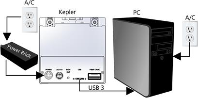
1. After receiving your Kepler, unbox all components.
2. Place the camera where it will be operated.
3. Plug in USB 3-Micro B cord to the camera and screw in the holding pins. Connect the USB 3 end into your computer.
a. You should use a 3.0 USB port on your computer, commonly labeled with a small SS next to it.
4. Connect 12-Volt power supply to camera.
a. After the power supply is connected to camera, then connect the power supply to a wall socket or AC power Strip. Ensure power supply is plugged into camera before being plugged into AC power.
b. If you plugged into a power supply you can turn the power supply on now.
c. When the camera has power the fan should start.
5. Start FLI Pilot, in a few moments the camera should connect and be recognized.
a. If the top middle menu says Kepler SCMOS Camera(4040 or 400) – Individual Serial Number – Connected (Super Speed), then you are ready to proceed.
6. For more Set up information please go here.

III. Set Up

IV. Taking an Image
1. Open FLI Pilot
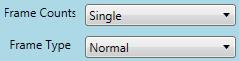
2. Expand the Grab Control menu.
3. The default Grab modes should be Frame Counts: Single and Frame Type: Normal.
a. For details of the different grab modes please go here.
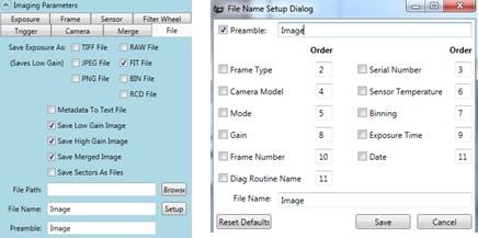
4. To automatically save image:
a. Click Save to File on the Grab Control menu.
b. Select file type (ex. FIT).
c. Select the 3 image types (Save Low Gain Image, Save High Gain Image, Save Merged Image)
d. Specify file path (where the image will be saved to).
e. Select the Preamble box and add Image.
f. For more information, visit: https://www.flicamera.com/kepler/keplermanual/File.html
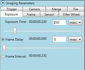
5. To set exposure time:
a. Click Exposure on the Grab Control Menu.
b. Enter your desired exposure time within the Imaging Parameters menu.
I. If you encounter a white image with a mean of 4095, decrease your exposure time.
c. For more information, visit: https://www.flicamera.com/kepler/keplermanual/Exposure.html
6. Set cooler temperature:
a. Click Cooler Temp in the Grab Control menu to show the Camera menu.
b. Turn on Cooler Temp and enter your desired temperature value.
c. For decreased Dark Current Growth, operate the camera at a lower temperate, ideally -10c. This ensures for a cleaner image.
d. It takes 5 degrees per c to cool, therefore it will take a few minutes to reach -10c.
e. Wait for the camera to reach your operating temperature before continuing.
f. For more information, visit: (https://www.flicamera.com/kepler/keplermanual/Camera.html )
7. Capture an image:
a. Click Grab Normal Frame, under the Grab Control menu, to take an image.
I. If the previous steps were followed, the image was saved to your desired location.
II. You may revisit any of the previous steps to adjust your image.

V. Reviewing Image
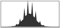
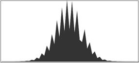
1. Image characteristics are shown in the histogram at the bottom left of FLI Pilot.
a. This displays image mean, standard deviation, mode, etc.
b. If you are viewing the Merged image histogram it may have a comb look, like the image below. This is
a normal outcome and is due to the truncation and rounding of the individual pixels values.
Once you have captured an image please proceed to the next step.

VI. Stacking Images (Master Dark) for Fixed Pattern Noise (FPN/PRNU)
Correction
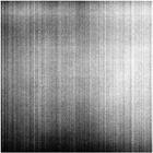
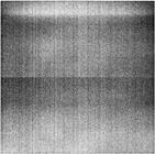
1. The next step takes a number of Dark images and stack them together to produce an average image.
Please see below for normal dark images.
Low Gain Image (Single) High Gain Image (Single)
2. If your camera does not have a shutter please block light from your camera.
3. If your camera does have a shutter go to the Imaging Parameters menu and click on the Camera Tab.
a. Activate the Manual Shutter Control Enabled box.
b. Ensure the Close box is checked, this should close your shutter.
4. Similar to the step above, please update the Preamble line, under the Imaging Parameters menu and the
Camera tab, to “Stacked”.
5. Once you are able to take a dark image, navigate to the Tester Routines menu
a. Select Stack Frames from the Routine: list.
b. Change the Frame Count to 25
c. Ensure the exposure time and units are the same as your previously captured image.
6. Press the Start button next to Stacked Frames.
a. When finished the new Stacked Low/High/Merged images are saved then displayed.
7. It is recommended that stack frames be taken at a range of times (100msec, 500msec, 1 sec, 5 sec
10sec). These can be used for image correction of exposure which have similar times. For the best results,
FLI recommends using correction frames which exactly equal the exposure time. These can be acquired at
any time.
8. This process may also be used to gather Stacked Flats which may be used in 3rd party imaging software
for further image correction.


VII. Correcting the Image for FPN
1. Under the Tester Routines menu, select the Frames Difference routine.
2. Select the Browse button next to the Reference Files:
a. Select the Stacked High gain image file that was created and saved earlier.
3. Select the Browse button next to the Source File:
a. Select the Image High gain image file that was created and saved earlier.
4. Once both High gain image files have been selected, press the Start button.
a. This will create a corrected High Gain image file without the fixed pattern noise of the sensor.
5. Manually save this image. Please select File, Save As.
a. Ensure that the Save As Type is .Fit
b. Select the path and file name as appropriate. A file name of “Corrected Image” will work.
6. Select the Browse button next to the Reference Files:
a. Select the Stacked Low gain image file that was created and saved earlier.
7. Select the Browse button next to the Source File:
a. Select the Image Low gain image file that was created and saved earlier.
8. Once both Low gain image files have been selected, press the Start button.
a. This will create a corrected Low Gain image file without the fixed pattern noise of the sensor.
9. Manually save this image. Please select File, Save As.
a. Ensure that the Save As Type is .Fit
b. Select the path and file name as appropriate. A file name of “Corrected Image” will work.
10. Once the Low and High gain Corrected Images have been saved, proceed to the next step, producing the
HDR image.
For further information on Pilot's routines please see Tester Routines

VIII. Producing a 16-bit High Dynamic Range (HDR) Image
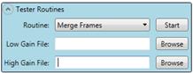
1. Under the Tester Routines menu please select the Merge Frames routine.
2. Press the Browse button next to the Low Gain File:
a. Select the Corrected Image_Low image.
3. Press the Browse button next to the High Gain File:
a. Select the Corrected Image_High image.
4. Press the Start Button.
a. This will produce a new Merged Image – Manually Merged Image.
5. Manually save this image. Select File, Save As.
a. Ensure that the Save As Type is .Fit
b. Select the path and file name as appropriate. A file name of “Corrected Image” will work.
6. This completes your tutorial on taking your camera from the box to production of corrected images.
Automatically Correcting Images for FPN (Steps VII & VIII Automatic)
1. After you have created and saved the Stacked Dark Image in step VI you may continue, this section
replaces steps VII and VIII.
2. Go to the Imaging Parameters menu and click on the Merge tab.
3. Click on the box next to Subtract Reference Files to enable automatic correction.
4. Click the Browse button next to the High Ref File: and select the Stacked High Gain image obtained from
Section VI.
5. Click the Browse button next to the Low Ref File: and select the Stacked Low Gain image obtained from
Section VI.
6. Once steps 3-6 are complete each image will automatically have the Fixed Pattern Noise removed prior to
display in Pilot.
7. If automatic file saving is enabled the corrected images will be saved.

Optional Settings
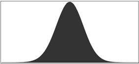
Correction of Merge Histogram
Normal Histogram Corrected Histogram
1. Depending on which gain pairs are selected the Merged image histogram may show a comb effect, as
demonstrated below. This is due to rounding and truncation of pixel values as you move from the High/Low
gain images 12bit 0-4095 pixel count up to the Merged images 16bit 0-65535 pixel count.
2. If you wish to have a histogram without the comb effect please follow the steps below.
a. Go to the Imaging Parameters menu and click on the Merge tab.
b. Enable the box next to Correct Histogram.
c. Click the Apply button below that.
Running Other Gains? Use Merge Calculate
1. If you are using Gains other than the defaults or if your merged image needs further calibration please run
the Merge Calculate routine, following the instructions below.
2. Go to the Tester Routines menu and select the Merge Calculate routine.
3. Select the button next to 1, above the Temperature of -10.
4. Select the Gain Pair (Low and High) that you wish to run.
5. Press Browse next to Output Path:
a. Select a location to save the output file to (this file is only for reference).
6. Press Browse next to Region File:
a. Select the MergeCalculateRegionFile.csv that was saved earlier during the installation steps.
7. Press the start button.
8. Once the results box says “Straight Line Found” the process has completed.
9. Click the box that says Save As Defaults
10. Your merged calibration has been completed and you may resume image acquisition.