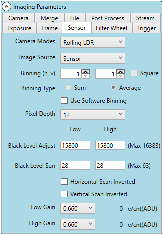

Sensor Settings
Camera Modes
CMOS cameras allow four camera modes for selection:
Rolling LDR, Rolling HDR, Rolling LDR - LDC, and Rolling
HDR - LDC.
These modes operate the camera with rolling shutter
LDR and HDR define the dynamic range of the mode of
operation.
LDC denotes Low Dark Current mode which decreases the
full well capacity of the photosensors, decreasing the number
of electrons that accumulate when the pixels are not exposed
to light. As a result, the dark current accumulated is
decreased, allowing better long exposure images.
Image Source
Typically, the sensor is the image source. "Row Test Pattern"
and "Col Test Pattern" are useful for camera diagnostics and
are not typically used for any purpose other than such.
Binning
Binning is the process of combining adjacent pixels into a large pixel. The combining occurs either as a feature
of a sensor or via Pilot post image readout.
Hardware Binning
The only Kepler camera to support hardware binning is the KL4040. While most Kepler sCMOS sensors do
not allow binning, some CMOS sensors do, but the binning must be the same in each direction. For CMOS
sensors that allow binning, enable the Square checkbox to bin horizontally and vertically equally. CCD
sensors permit unequal binning, so the Square checkbox is not required for such cameras.
The two primary benefits of hardware binning are a decrease in transmitted data which leads to a potential
increase in FPS and the ability to have a larger well size.
Software Binning
It is also possible to run Binning after the image is captured using software in Pilot. By using the software to
accomplish the binning you are not limited to a square bin and can instead accomplish a rectangular binning.
Any image can thus go through the binning process.
The primary benefit of software binning is an increase in the Signal to Noise Ratio however this comes at the
cost of Sampling Density and therefore Resolution.
To set binning options, first, check Square if required or desired. Then, type or use the up/down buttons to
adjust the values. On the left is horizontal (h) and on the right is vertical (v). These options are displayed on the
Binning Type
Words regarding sum and average binning.
Pixel Depth
Pixel depth describes the number of bits used to represent the sensor. It is used to represent a sensor pixel and
is determined by the sensor. Typical output is 16 bit. Using a lower number truncates the data in the camera for
faster transmission.
The KL400 sensor does not allow for changing the bits per pixel.
For cameras with sensors that offer pixel depth modifications (Interline and Full Frame), the available selections
are displayed.
Black Level Adjust
Black level is a measure of a reference voltage. This number is normally defined by non-imaging pixel areas of
the sensor, however, the black level adjust option allows a secondary influence on this reference voltage. Black
level adjust can be increased to increase the pixel values within your image. If you take a 10msec dark and look
at the minimum pixel value, you can adjust it up or down by increasing or decreasing the black level adjust. This
can be useful to ensure that you are not clipping your darkest pixels.
Black Level Sun
Very bright areas in an image can cause saturation of the pixel well and "overflow" resulting in that area looking
dark. This option allows for mitigation of that effect. Enabling this feature increases noise. Increasing black level
sun reduces the black sun effect, while increasing noise.
A maximum value of 63 can be selected which will produce quite a lot of noise while correcting the black sun as
best it can. If a level this high is required to correct your image, it is recommended to correct the capture rather
than this value specifically. adjusting the cameras aperture and exposure, and removing the intense bright light
from the sensors FOV will all improve the black sun effect without significantly impacting image quality.
Horizontal Scan Inverted
The scan direction reflects the movement of the rolling shutter. The default horizontal direction is left to right.
When "Horizontal Scan Inverted" is enabled, the read direction is right to left. This changes the pixel order in the
data file.
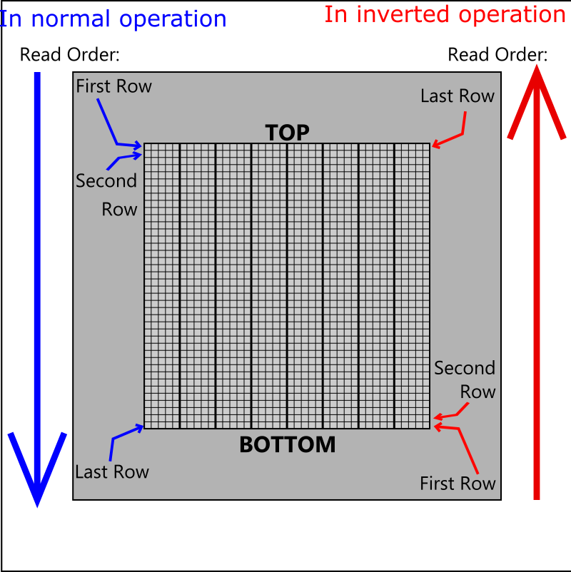
Vertical Scan Inverted
The scan direction reflects the movement of the rolling shutter. The
default vertical direction is from top to bottom. When "Vertical Scan
Inverted" is enabled, the read direction is from bottom to top. This
changes the pixel order in the data file.
LDR and HDR Gain
Dynamic range can be assigned for both the high and low gain images.
LDR images are often captured with a low gain of 1.85 (KL400). HDR
images are often captured with a low gain and high gain of 1.29 and 7.25
(KL400) or 2.8 and 16.5 (KL4040).
Global Gain
the global gain option allows the user to define the gain setting for both
low and high gain images.

Finger Lakes Instrumentation, a division of IDEX Health & Science
1250 Rochester St.
Lima, New York 14485
1250 Rochester St.
Lima, New York 14485
Phone: 585-624-3760
Email: IHSKeplerSupport@IdexCorp.com
Web: www.flicamera.com
Email: IHSKeplerSupport@IdexCorp.com
Web: www.flicamera.com
©2023 IDEX Health & Science