

©2023 IDEX Health & Science LLC
Phone: 585-624-3760
Email: IHSKeplerSupport@IdexCorp.com
Web: www.flicamera.com
Email: IHSKeplerSupport@IdexCorp.com
Web: www.flicamera.com
Finger Lakes Instrumentation, a division of IDEX Health & Science LLC
1250 Rochester St.
Lima, New York 14485
1250 Rochester St.
Lima, New York 14485
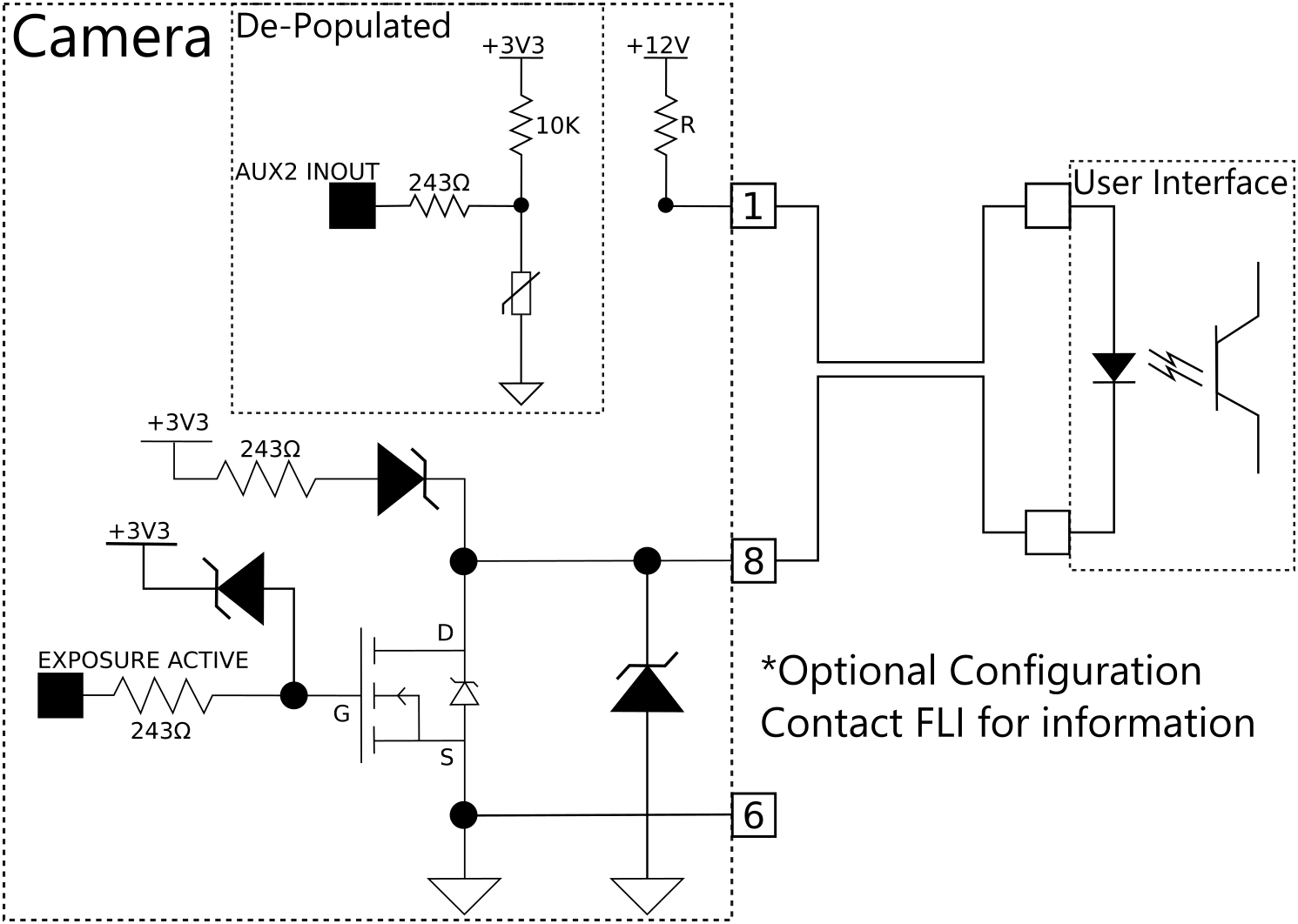
This configuration uses a 12V source provided by pin 1 to drive an optocoupler.
For more information see Pin 1 and Pin 8. Contact FLI for more details.

Pin 1 and 8 - Optional Optocoupler Configuration
Figure 7. Exposure Control
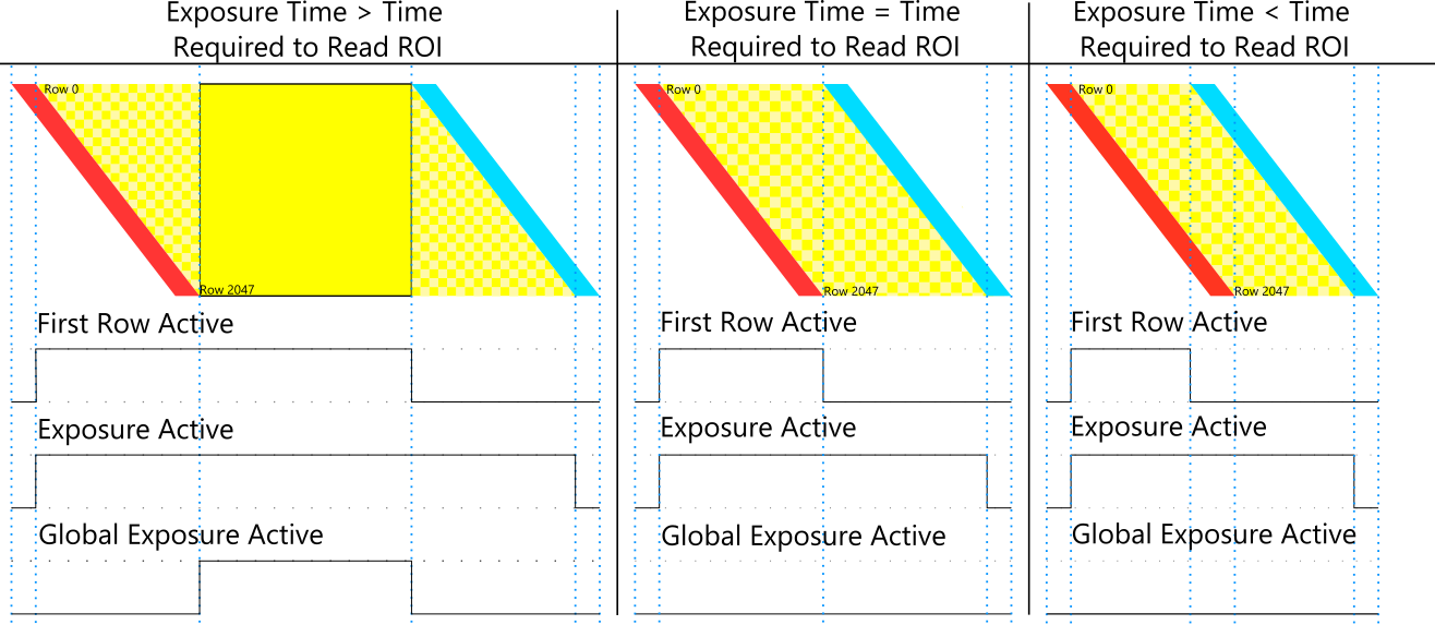
Pin 8 will output a signal indicating the state of exposure the camera is in. This external signal can be used to control external devices directly from the exposure state of the camera. This indicator can be used for timing instruments properly, and can be configured in the following modes to vary the output based on specific moments in the sensors process.
First Row Active (Default):
In First Row Active mode, the output signal is high during the first rows' exposure in a single frame. (Figure 7)
The length of the signal is dependent on the first rows exposure time. The exposure time can be set in the software by the user.
This mode maximizes frame rates, but results in overlap of frames due to the rolling shutter effect.
Exposure Active:
In Exposure Active mode, the output signal is high when any row in a single frame is exposing. (Figure 7)
The length of the signal is dependent on the time between the start of the first rows' exposure and the end of the last rows' exposure.
It is not possible to achieve maximum frame rates in this mode, but frame overlap is avoided.
Global Exposure Active:
In Global Exposure Active mode, the output signal is high when all rows are simultaneously exposing.
The length of the signal is dependent on the time between the start of the last rows' exposure and the end of the first rows' exposure.
This mode takes advantage of the speed and low noise capabilities of the rolling shutter but eliminates motion artifacts. (Figure 7)
Exposure Indicator


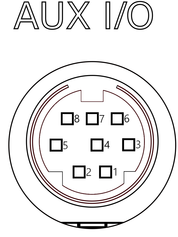
8-Pin Connector
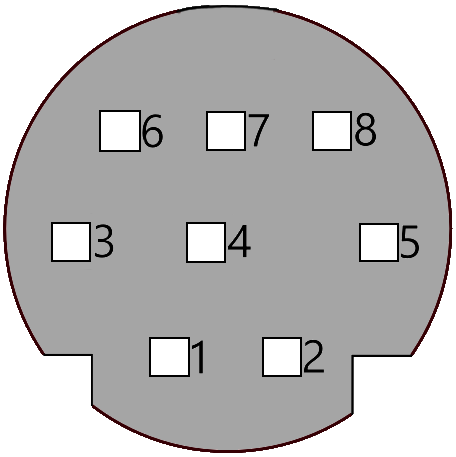
The Kepler Imaging Systems have an eight pin AUX connector as shown in Figure 1 and Figure 2 with each pin described below. Figure 1 is from the viewpoint looking at the cable. Figure 2 is from the viewpoint looking at the camera.
The tables below summarizes the pins on the 8-pin connector by pin number and by description in alphabetical
order.
| Pin | Description |
| 1 | Aux2_InOut |
| 2 | Aux1_InOut |
| 3 | External Trigger |
| 4 | Aux3_InOut |
| 5 | Shutter Open |
| 6 | Ground Reference |
| 7 | Aux4_InOut |
| 8 | Exposure Active |
| Description | Pin |
| Aux1_InOut | 2 |
| Aux2_InOut | 1 |
| Aux3_InOut | 4 |
| Aux4_InOut | 7 |
| Exposure Active | 8 |
| External Trigger | 3 |
| Ground Reference | 6 |
| Shutter Open | 5 |


Pin 1 - Aux2_InOut
Pin 1 of the 8 Pin connector is a 12V supply.
By default, there is a 243 Ohm series pullup resistor to 12V. This configuration allows use of the Kepler Image Time Stamp (KITS) module which requires 12V for operation.
An optional configuration is available to use pin 1 as an auxiliary IO connection. With the optional configuration, there is a 243 Ohm series resistor between the connector pin and the input/output driver. There is also a pullup of 10K to 3.3V.
Note: Installation of this configuration adds an additional aux IO, but removes the ability to use the KITS module.
The optional configuration can be assembled by FLI upon ordering. Contact FLI for information.
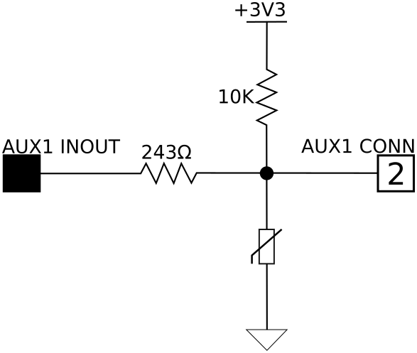
Pin 2 - Aux1_InOut
Pin 2 of the 8 Pin connector is auxiliary Input/Output 1.
There is a 243 Ohm series resistor between the connector pin and the input/output driver. There is also a pullup of 10K to 3.3V.
This input/output driver is 3.3V LVCMOS compatible. The direction is controlled via the API. The state is controlled by the user or the API, depending on the direction.


Pin 3 - External Trigger
Pin 3 of the 8 Pin connector is the external trigger input signal.
There is a 243 Ohm series resistor between the connector pin and the input driver. There is a 10K Ohm pullup resistor to 3.3V. The state is controlled by the user.
See External Triggering.
Pin 4 - Aux3_InOut
Pin 4 of the 8 Pin connector is auxiliary Input/Output 3.
There is a 243 Ohm series resistor between the connector pin and the input/output driver. This input/output driver is 3.3V LVCMOS compatible. The direction is controlled via the API. The state is controlled by the user or the API, depending on the direction.
This pin can be programmed as a general purpose I/O or as UART in which case this pin becomes the RX for the UART.
Default configuration operates as a UART, however, can be configured to operate as an IO upon request.


Pin 5 - Shutter Open
Pin 5 of the 8 Pin connector is the shutter_open output signal.
There is a 243 Ohm series resistor between the connector pin and the output driver. The output driver is 3.3V LVCMOS compatible.
Default state is shutter closed, 0V.
Pin 6 - Ground Reference
Pin 6 of the 8 Pin connector is camera ground. All other pins on this connector are referenced to this pin.
Pin 7 - Aux4_InOut
Pin 7 of the 8 Pin connector is auxiliary Input/Output 4.
There is a 243 Ohm series resistor between the connector pin and the input/output driver. This input/output driver is 3.3V LVCMOS compatible. Direction is controlled via the API. The state is controlled by the user or the API, depending on the direction.
This pin can be programmed as a general purpose I/O or as UART, in which case the pin becomes the TX for the UART.


Pin 8 - Exposure Active
Pin 8 of the 8 Pin connector is the exposure active output signal.
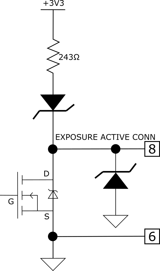
There is a 243 Ohm pullup resistor to 3.3V. There is a FET switch to ground. The state is controlled by the camera controller. The default state is low.
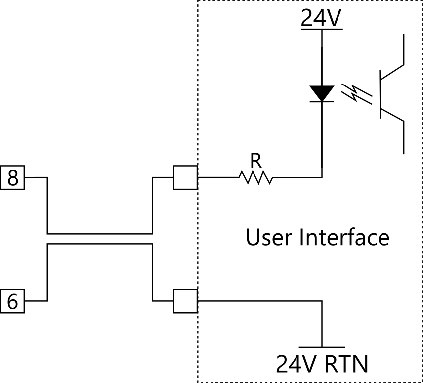
This pin is configured to be either a logic output or a driver for optocouplers. Possible optocoupler setups are shown in the figures to the right.
Figure 6a. The internal configuration of pin 8.
Figure 6b. A possible configuration that uses a 24V supplied by the user to drive an optocoupler.
Figure 6c. Another possible usage for pin 8 to use an optocoupler driven by the 3.3V supplied by the camera.
Figure 6b. A possible configuration that uses a 24V supplied by the user to drive an optocoupler.
Figure 6c. Another possible usage for pin 8 to use an optocoupler driven by the 3.3V supplied by the camera.
Figure 6a
Figure 6c
Figure 6b
Exposure Active is the default configuration for pin 8's output. To change this option, one may use LibFLIPro, the SDK behind FLI Pilot, to program the exposure active signal type. The function FPROAuxIO_SetExposureActiveType(iHandle, eType) is used for this operation and discussed in greater detail in the SDK documentation. The SDK and SDK documentation is available at flicamera.com. The most up-to-date information can be requested through FLI.
Figure 1. Male AUX Connector (Looking at Cable)
Figure 2. Female AUX Connector (Looking at Camera)